


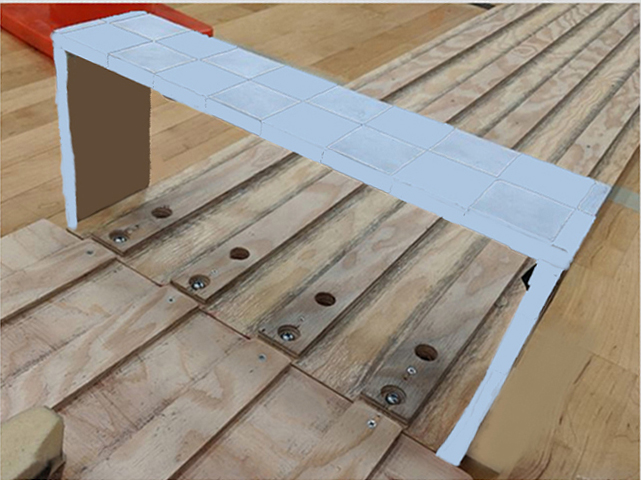
Some time in the 1980s I was approached by a Ham Radio friend to design a photofinish system for the Boy Scouts Pinewood Derby. This is a model car race track that consists of a wood track on an inclined plane. The scouts build their cars from a block of wood, wheels, and nails for the axles. There are specifications to qualify such as size and weight. The cars are rolled down the inclined track to the finish line. My objective was to design and build an electronic sensing device that would display which lane number had the car that finished first, second and third. The picture above is a four lane track similar to the one used by my friends scout troop. Ours had only three lanes.
My system had the overhead canopy over the finish line. I installed three focused light sources in the canopy shining down on the three accurately placed holes in each track. Under the holes I mounted phototransistors looking up at the lights. When the car passed over the hole, it blocked the light and the phototransistor turned off.
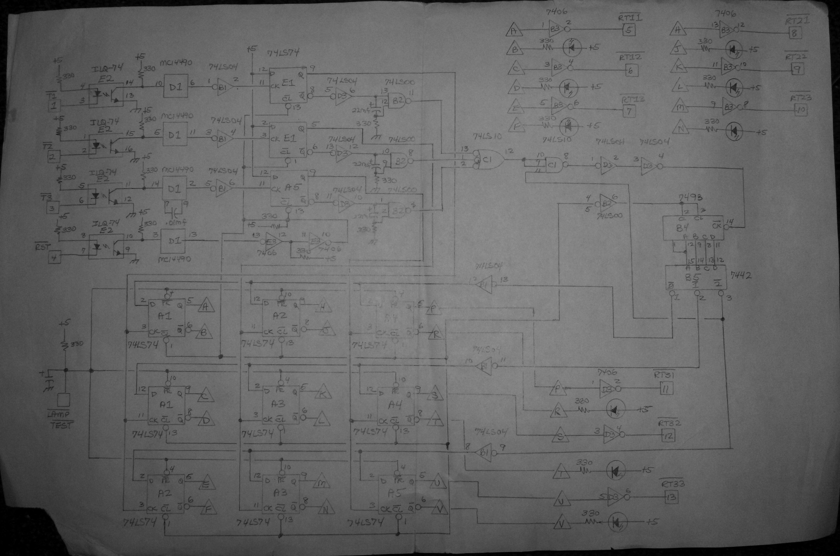
Here is the only diagram I have of the circuit I designed. I used 74LSxx series digital ICs, ILQ74 Optoisolators and 9 solid state relays. The "scoreboard" consisted of three columns of three rows of 9 watt incandescent lights. The top row was red lights indicating First Place. The second row was green lights indicating Second Place. The third row was blue lights indicating Third Place. The 3 columns represented the Track Number.
Starting at the top left, the ILQ-74 Optoisolators are connected to the phototransistors on the track. The ILQ-74 provides noise immunity from signals that could appear on the long cable between the track and the display. They feed an MC14490 IC which is a contact bounce eliminator, further creating noise immunity and preventing falsing of the sensor signals. One at a time, the track signals are latched into the D Flip-flops at E1 and A5. B2 provides a pulse to be counted so we can count the track places. Once a track is latched it produces only one counting pulse. The pulses are counted by the 7493 at B4 and decoded to decimal by the 7442 at B5. The output of B5 gives us the track number. The decoder provides 0, 1 and 2 for lanes 1, 2 and 3. There are nine D Flip-Flops at A1, A2, A3, A4 and A5. They are arranged in the same three column, three row format as the "scoreboard" lights. Initially they and the lane counter are all reset with the reset switch. Since the count is at zero, the top row of D Flip-Flops is enabled. When the first car crosses the finish line the lane the car is in will clock one of the D Flip-Flops in the top row which is in the column that corresponds to the lane the first place car is in. Next, the count advances to 1. This enables the second row of D Flip-Flops. When the second car crosses the finish line the lane the car is in will clock one of the D Flip-Flops in the middle row which is in the column that corresponds to the lane the second place car is in. Then the count advances to 2. This enables the thrid row of D Flip-Flops. When the thrid car crosses the finish line the lane the car is in will clock one of the D Flip-Flops in the bottom row which is in the column that corresponds to the lane the third place car is in. The nine solid state relays operating the light bulbs are connected to the nine D Flip-Flops through 7406 open collector inverters. There are nine LEDs on the board that will show the "scoreboard" finish places.
To test the operation I used a piece of cardboard with a straight edge. I passed the cardboard through the finish line at an angle. The display showed first, second and third places for tracks 1, 2 and 3 respectively. Next, I reversed the angle of the cardboard. Now the display showed third, second and first places for tracks 1, 2 and 3. Finally I passed the cardboard through the finish line in parallel with the sensors, simulating all cars crossing at the same time. Typically, this test yielded a tie with two cars at first place and the other at second place. I never was able to produce a three-way tie. That could possibly be related to minute discrepancies in the drilling of the holes in the track for the sensors or discrepancies in the tolerances of the electronic components .
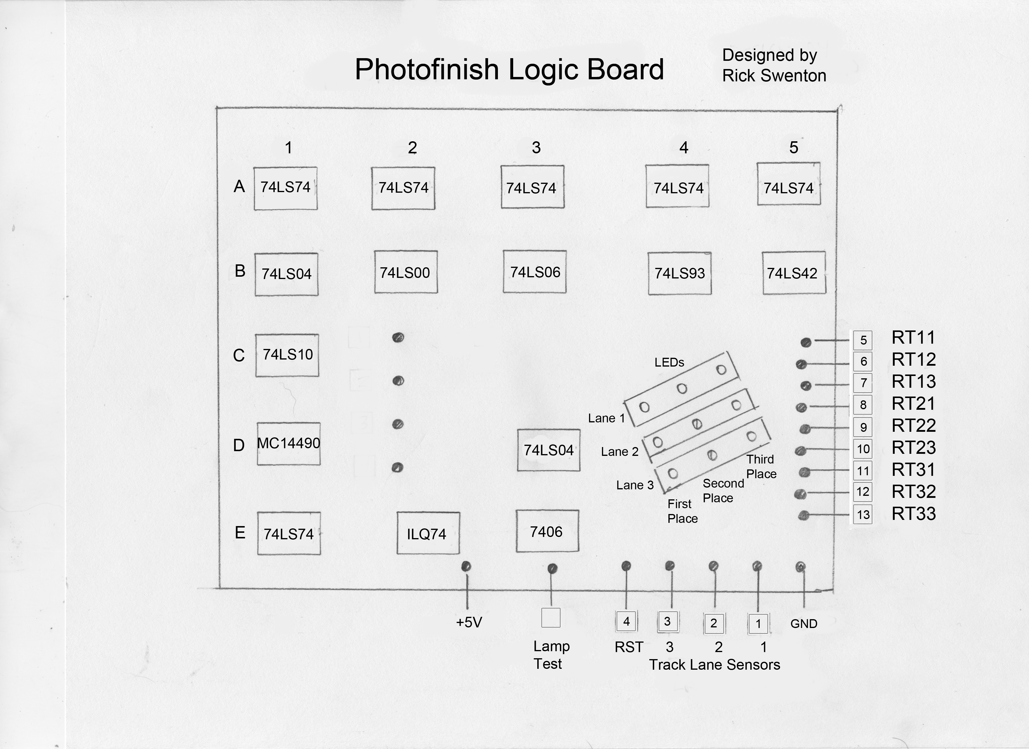
This is a pictoral of the circuit board. The lane sensors connect to points 1-2-3 and GND. The nine solid state relay control lines connect to the RT points. Pin 5 is for Relay Track 1 First Place lamp (RT11). Pin 6 is for Relay Track 1 Second Place (RT12). Pin 7 is for Relay Track 1 Third Place (RT13) and so on.
Unfortunately I never took any photos of this project. The complex logic could be easily replicated today in software with an Arduino sketch programmed in C and running on a $12 Arduino Uno board.