


Old School TTL Project
In 1980 I decided to design a digital clock that could produce Westminster Chimes. I did it the old fashioned way using TTL logic ICs, Op-Amps and FETs. The first thing needed was a sequencer that would produce triggering signals for the four tone chimes in the proper order, duration and speed.
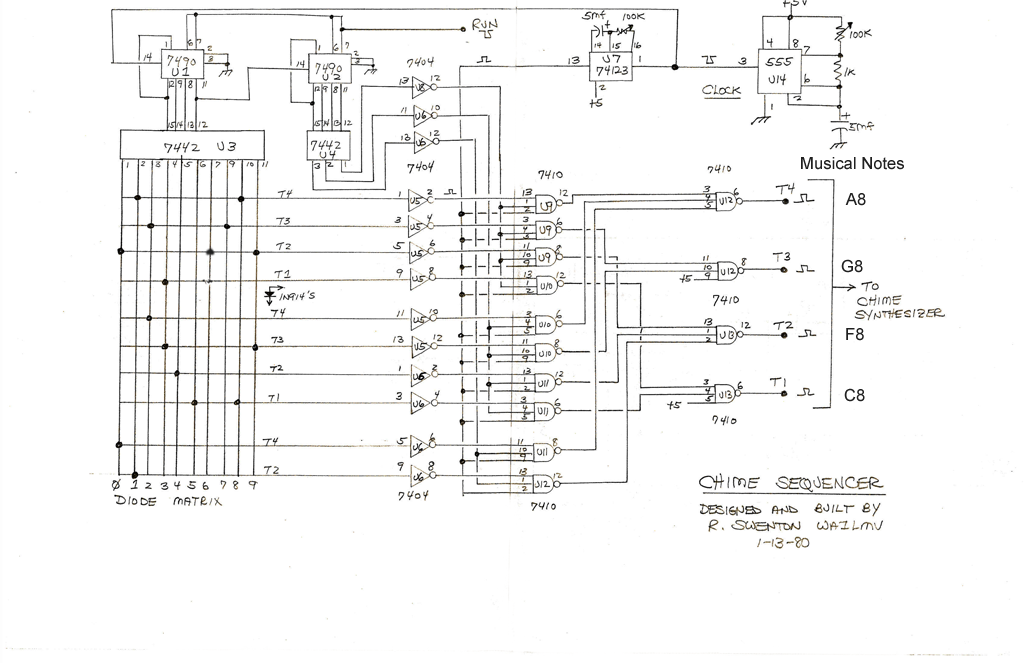
The diodes in the matrix in the lower left are arranged according to the sequence of tone pitches. T1 is the lowest pitch. T4 is the highest pitch. If we were generating the tones in the key of F, the notes would be F A G C (2 beat pause) F G A F (2 beat pause) A G F C (2 beat pause) C G A F. The decade counter at U1 counts the sequence. U3 decodes the counter's BCD into decimal to drive the matrix.
There are only 10 output lines from U3 but there are 22 sequence positions, notes and pauses. The matrix is arranged as one column and three rows. The first two rows are 4 notes wide. The last row only has 2 notes. While U1 counts the column position, U2 counts the row. U9 - U12 decode the columns and rows to produce the tone gates T1 through T4.
The adjustable time delay provided by U7 determines the duration of the chime pulse.
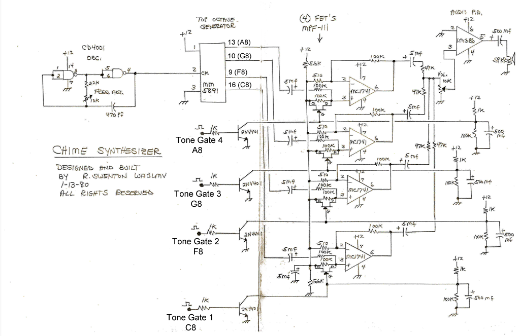
Next is the Chime Synthesizer Board. The CD4001 oscillator determines the overall pitch in which the chime tones will be played. The top octave generator provides the musical notes. We will only be using C F A and G. These notes are relative to each other and will not actually be C F A and G unless the frequency of the CD4001 is set correctly. The 4 tones are fed into 4 op-amps and gated by FETs. The attack of the tone is quick. The release of the gate is determined by the 4 RC networks with the 500mf capacitors and is slow. This simulates a hammer strike of a chime. The 4 tones are mixed into the volume control. The LM386 audio amplifier drives a small speaker.
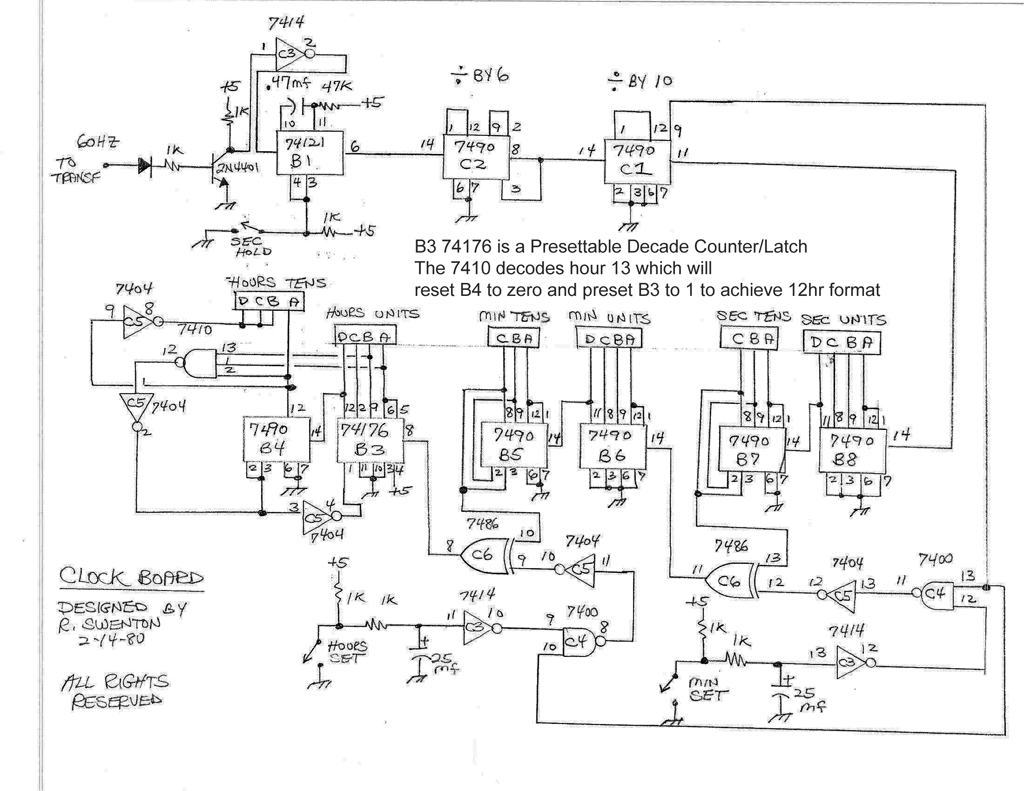
Now we move on to the Clock Board. A 60 Hz signal is derived from the power transformer secondary and shaped by C3 and B1 into a square wave pulse. A seconds hold switch is available to stop the clock to synchronize to an reference time. C2 divides the pulses by 6 and C1 divides by 10 to produce a 1 Hz signal to start counting seconds. From here, 6 decade counters B3-B8 count the seconds, minutes and hours. B7 and B5 are wired as divide by 6 so they count 0 to 5. For the hours counters at B3 and B4, the extra inverters and nand gate provide 12 hour format. When the BCD value of B4 is 1 and B3 is 3, the time would have advanced to 13:00:00. The 13 is decoded, resets B4 to 0 and presets B3 to 1, so the time changes from 13:00:00 to 01:00:00 to display the time in a 12 hour format. The BCD outputs of the counters is fed to the Display Board.
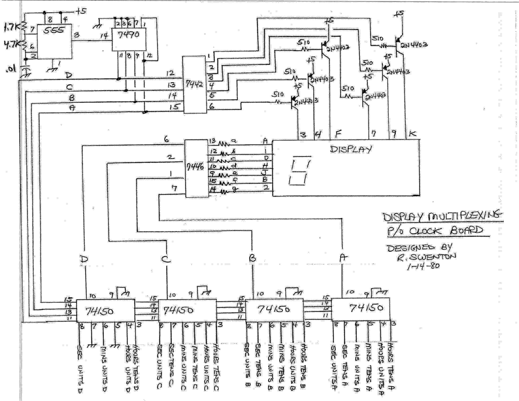
For the Display Board I used a standard six digit LED clock display module. This is a multiplex system. The 555 IC is the multiplex clock. It needs to be running fast enough so that the display is not seen to be flickering. The 7490 is wired as a divide by 6 and decoded by the 7442 to provide the digit enable signals. The 7490 also drives the four 74150 multiplexers. The BCD signals from the clock board counters enter here. All of the LSB A signals come in to the right 74150. All of the MSB D signals come in to the left 74150. As the 7490 counts from 0 to 5 the appropriate ABCD signals are decoded by the 7446 and sent to the display. At the same time, the 7490 count from 0 to 5 is enabling the correct LED display to show the correct ABCD time value for that digit and the right time in the sequence.
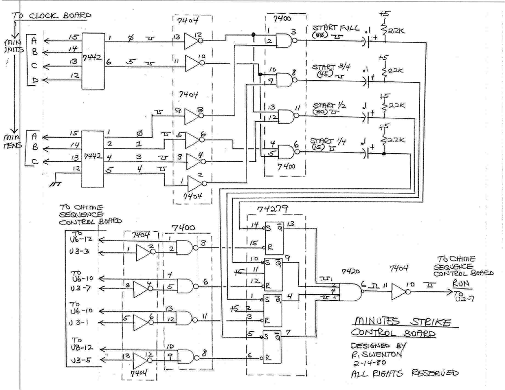
As if this is not complicated enough, we have the Minutes Strike Control Board. The whole Westminster Chime sequence is programmed into the diode matrix on the Chime Sequencer Board. But we only play a part of the sequence depending on the time. The first 4 notes are played at 15 mins past the hour. The frist 8 notes are played at 30 mins past the hour. The frist 12 notes are played at 45 mins past the hour. And The all 16 notes are played at the top of the hour. This board decodes the BCD time from the Clock Board into decimal with the two 7442 ICs. Then the 7400 IC decodes the decimal signal into a signal corresponding to a clock minutes time of 0, 15, 30 or 45. Those signals in turn set one of the 4 latches in the 74279 IC which starts the chimes running on the Chime Sequence Control Board. The inputs coming in to the 7404 and 7400 ICs on the lower left are coming from the Chime Sequence Control Board. These signals will stop the chime sequence when the correct number of notes have been played based on the 0, 15, 30 and 45 minutes display. So the start of the melody is triggered by the minutes time becoming 0, 15, 30 or 45. The stopping of the melody is determined by how many notes have been played based on the note's position in the diode matrix.
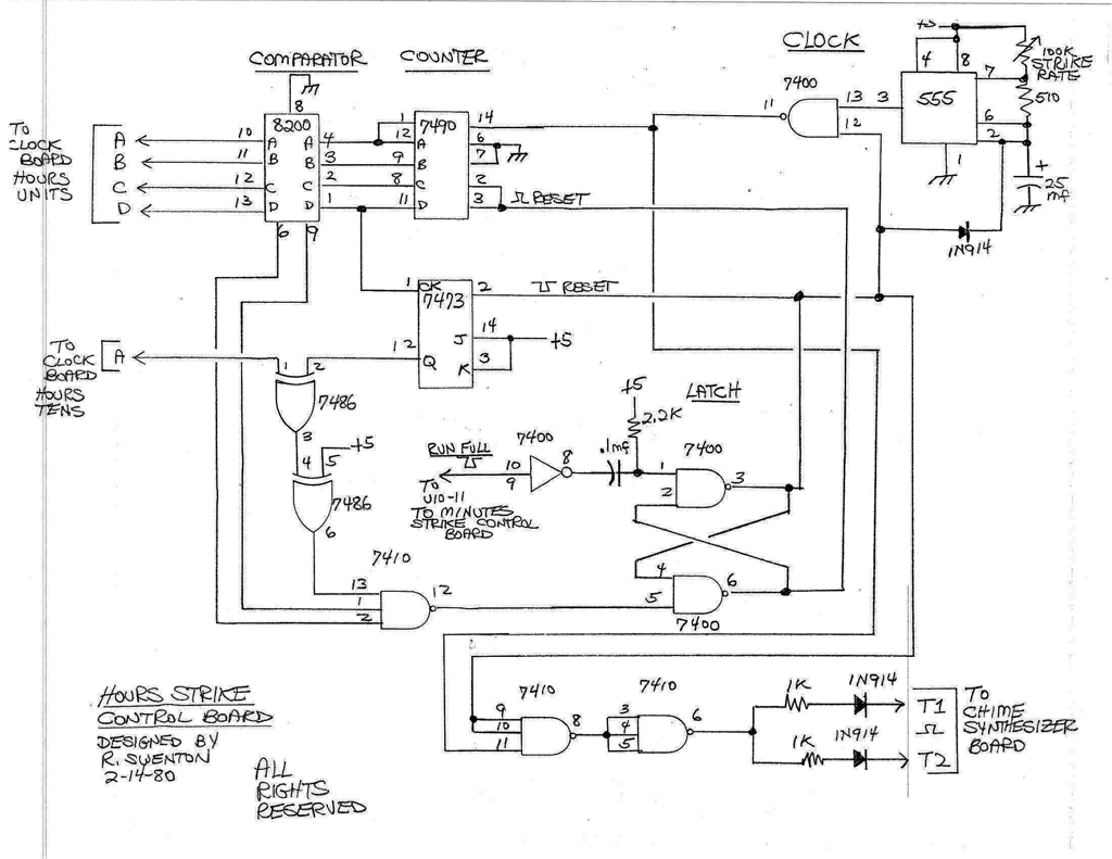
Finally, to add more complexity, we have the Hours Strike Control Board. After the chime sequence is played at the top of each hour we then need to chime the hour. The hourly chime starts after the Minutes Strike Control Board finishes playing the whole Westminster Chime melody and triggers the 7400 latch. The 555 provides the hourly chime pulse. The rate is determined by the Strike Rate Pot. Once the latch is set the outputs T1 and T2 will start striking the F and C pitches to chime the hour. The 7490 will start counting the chimes. The current hour BCD signals are sent into the 8200 comparator. When the comparator sees that the 7490 count matches the current hour in BCD the latch will be reset and the chimes will stop.
Yeah, back then this was overkill. Today we could do this all with a simple Arduino Uno and a managable sketch (Arduino computer program.) I may actually take on the challenge of doing it some day.